 ELECTRONAUTICS
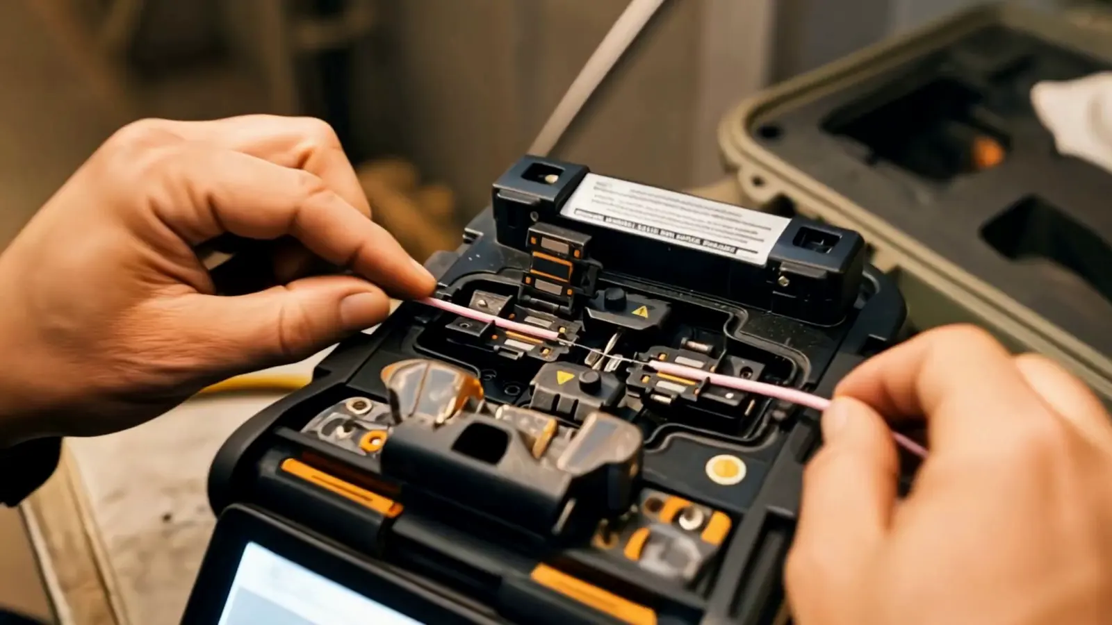
An OTDR measurement shows a fibre optic link as a trace over its length. Splices, connectors, tight bends and the fibre end appear with their location and loss. This shows where the link has losses and whether the splicing was done properly. For acceptance, many standards also require insertion loss to be measured.
01What does an OTDR measurement show?
It shows where along the link light is lost, and how much. The instrument sends short pulses of light into the fibre and analyses the light that comes back: the weak backscatter from the fibre itself and the reflections at connectors1. The travel time gives the location, the strength gives the loss.
The trace shows four things:
- The fibre: an evenly falling line. Its slope is the attenuation in dB per kilometre.
- Splices: a small step. A very good fusion splice can be so small that it is barely visible.
- Connectors and mechanical splices: a step with a peak in front of it, because light is reflected there.
- The end: a large reflection, followed by nothing but noise.
Short pulses give fine resolution, long pulses reach further1. On short links with closely spaced events, short pulses and a properly set-up instrument are therefore what matters.
02Which wavelengths are measured?
For multimode 850 and 1300 nm, for singlemode 1310 and 1550 nm, with 1625 nm in addition if required3. There is a practical reason for measuring at two wavelengths: longer wavelengths are more sensitive to bending and pressure. If an event is clearly larger at 1550 nm than at 1310 nm, this points to a bend or stress on the fibre, not to a bad splice1.
03Why do you need launch and receive fibres?
Because the OTDR is blind right at its port and otherwise cannot assess the first connector. The strong reflection at the instrument port is followed by a dead zone in which the instrument resolves nothing. The launch fibre moves the first connector of the link out of this zone and provides a section of trace in front of it as a reference1. The same applies at the other end: without a receive fibre, the loss of the last connector cannot be measured.
For singlemode, the FOA gives a launch fibre of 500 to 1000 metres2. That can be longer than the entire link on board. Leaving out the launch fibre, or choosing one that is too short, gives traces that cannot be evaluated properly, especially on short links.
04Why measure in both directions?
Because a measurement from one direction only can distort the splice value. Two fibres rarely backscatter exactly the same amount. If the light at the splice passes into a fibre with higher backscatter, the OTDR shows too little loss or even a ‘gain’. From the opposite direction, the same splice looks worse than it is1.
The true loss is the same in both directions. That is why both directions are measured and averaged. The FOA calls this the only way to assess splices in a link accurately1. So a ‘gain’ at a splice is not an instrument fault. It is caused by the difference in backscatter and disappears in the average of both directions.
05What values apply to splices and connectors?
The binding limits are in the project specification. For guidance, there are the maximum values of the TIA-568 standard and the typical values the FOA gives alongside them4:
| Parameter | Typical value | Maximum to TIA-568 |
|---|---|---|
| Fusion splice, singlemode | below 0.05 dB | 0.3 dB |
| Splice, multimode | 0.1 to 0.5 dB, about 0.3 dB on average | 0.3 dB |
| Connector pair | Singlemode factory-made 0.1 to 0.2 dB, multimode 0.2 to 0.5 dB | 0.75 dB |
| Fibre, singlemode | 0.4 dB/km at 1310 nm, 0.3 dB/km at 1550 nm | 1.0 dB/km indoor, 0.5 dB/km outdoor |
| Fibre, multimode | 3 dB/km at 850 nm, 1 dB/km at 1300 nm | 3.5 dB/km at 850 nm, 1.5 dB/km at 1300 nm |
For connector reflectance, the FOA gives these orders of magnitude: PC −30 to −40 dB, UPC −40 to −50 dB, APC −60 dB or better4.
Specifications often state a stricter value, for example ‘no more than 0.1 dB per fusion splice, averaged over both directions’. That is a contract value, not a value from a standard. If it is to apply, it must be in the contract, together with the wavelengths and the test method.
06Is an OTDR measurement enough for acceptance?
Not under many standards. They do not allow the loss of a link to be proven with the OTDR alone. What they require is insertion loss, measured end to end with a light source and power meter5. In TIA-568, this measurement is the basic test (‘Tier 1’) and the OTDR the supplementary test (‘Tier 2’)1,5.
The two measurements answer different questions. Insertion loss tells you how much light arrives at the end, in other words whether the link works. The OTDR tells you where the light is lost, in other words whether the work was done properly and where rework is needed.
On ships, the rules of the classification society also apply. Lloyd's Register, for example, requires an attenuation measurement on fibre optic cables before and after installation, with the record kept on board6. The installation standard IEC 60092-352 has also added requirements for optical fibre cables in its new edition of October 20257.
07How do you calculate the loss budget?
Fibre attenuation times length, plus the number of connectors times the connector loss, plus the number of splices times the splice loss, plus a margin if needed4. The result is the value that the measured insertion loss must not exceed.
An example using the TIA-568 maximum values for a singlemode link on board with 150 metres of fibre, two connector pairs and two splices:
| Item | Calculation | Loss |
|---|---|---|
| Fibre | 0.15 km × 1.0 dB/km | 0.15 dB |
| Connectors | 2 × 0.75 dB | 1.50 dB |
| Splices | 2 × 0.3 dB | 0.60 dB |
| Budget | 2.25 dB |
The example shows what counts on board. On short links the fibre itself hardly matters; connectors and splices determine the result. That is why clean end faces and good splices decide the outcome on short links.
08What belongs in the test report?
Under the FOA standard FOA-4, at least the date, the tester, the test instrument, the cable and fibre identification, the wavelengths and all traces3. It also makes sense to include the following, even though FOA-4 does not require it:
- Serial number and calibration date of the test instrument
- Pulse width, range, averaging time and index of refraction
- Length of the launch and receive fibres
- Measurement direction; for two directions, both traces and the average
- Event table with the location, loss and reflectance of every splice and connector
- Total loss, optical return loss and the assessment against the limit
- The measurement files in .sor format, so that the traces can be reopened in standard analysis software
With the measurement files, a later measurement can be compared directly with the old trace, for example when something on the link is modified years later.
09Which mistakes should you avoid in OTDR measurement?
These mistakes follow directly from the measurement technique:
- Measured without a launch fibre, or with one that is too short: the first connector lies in the dead zone and cannot be assessed.
- Measured from one direction only: splices appear as a ‘gain’ or worse than they are.
- Automatic analysis without a check: the instrument places events wrongly or misses them. A specialist has to look at the trace.
- OTDR instead of insertion loss: the trace does not replace the end-to-end measurement.
- Wrong index of refraction: the lengths, and with them the locations of events, are wrong.
- Ghosts on short links: strong reflections at connectors create apparent events that are read as breaks1.
- Dirty connectors: dirt on the end face makes loss and reflectance worse. Clean and inspect before mating.
10What should be agreed before the first splice?
So that nobody argues about values at the end, the shipyard and the electrical contractor agree the following beforehand:
- Fibre type and connector type of the links
- The measurement wavelengths
- Limits for splices, connectors and total loss
- Whether measurements are taken in both directions
- Whether insertion loss is measured as well
- The format of the test report and whether the measurement files are handed over
- What the classification society requires for the ship
11How we do it at Electronautics
We splice fibre optic cables on board and test them with OTDR. The result goes into the test report.
The OTDR shows where something is wrong on a fibre. Used correctly, that means: with launch and receive fibres, at two wavelengths, in both directions and together with the insertion loss measurement. If the limits are fixed in advance, every result in the test report can be assessed clearly.
Important
The values in this article are guide values from the Fiber Optic Association based on TIA-568. The limits in your ship's specification and the requirements of the classification society are binding.
Questions about this article: info@electronautics.de
Sources
- The Fiber Optic Association (FOA): Testing with an OTDR thefoa.org ↗
- FOA: OTDR – frequently asked questions (FAQ) thefoa.org ↗
- FOA standard FOA-4 for testing installed fibre optic links (as of January 2025) thefoa.org ↗
- FOA: Loss budget with guide values to TIA-568 thefoa.org ↗
- FOA: Accuracy of fibre optic measurements thefoa.org ↗
- Lloyd's Register, Rules for Ships, Pt 6 Ch 2 Sec 21 ‘Testing and trials’ (July 2022 edition) imorules.com ↗
- IEC 60092-352:2025, Edition 4.0, contents and changes cdn.standards.iteh.ai ↗
As of 17 October 2026