 ELECTRONAUTICS
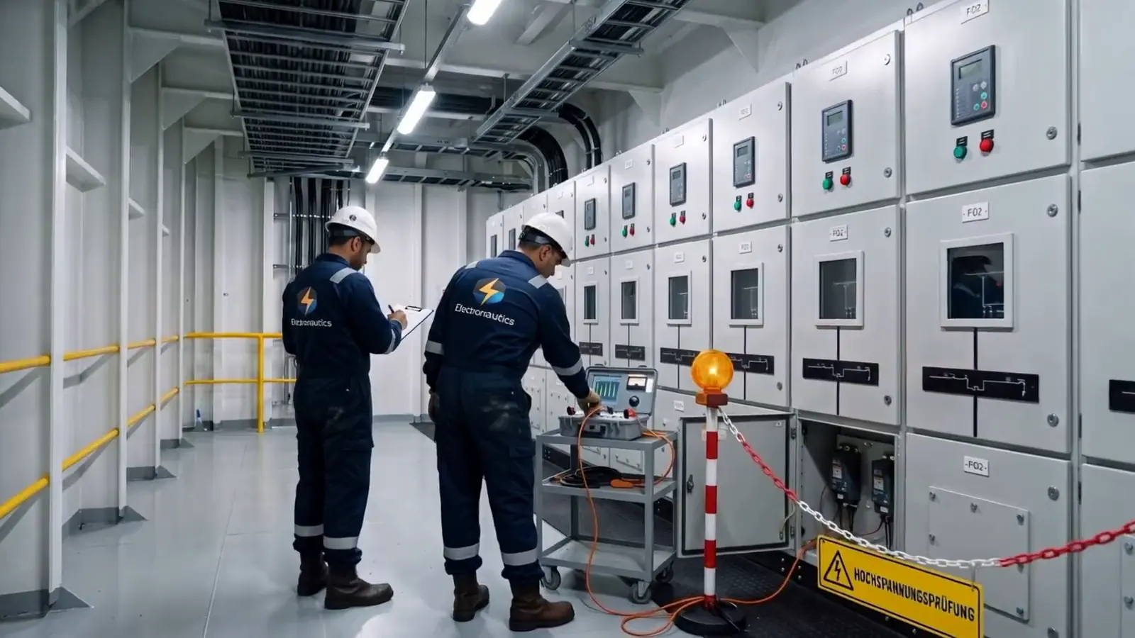
Before an HV cable goes into service on board, every completed cable is tested together with its terminations: first the insulation resistance test, then the voltage withstand test, then earthing and a second insulation resistance test. That is what the IACS requirements applied by IACS members call for. Which method, which voltage and which duration apply depends on the classification society and the cable manufacturer.
01What counts as high voltage on board?
AC systems above 1 kV and up to 15 kV. IEC 60092-503 and IACS UR E11 call this range “high voltage”1,3. Onshore, the same range is usually called medium voltage. On board, examples are 6.6 kV or 11 kV systems.
Cables are designated with two voltages, for example 6/10 kV. The first figure is U0, the voltage between conductor and screen. The second is U, the voltage between two conductors. Test voltages usually refer to U0.
02How are high-voltage cables tested on board?
Under IACS UR E11, every completed cable with its accessories is given a voltage withstand test before commissioning, preceded by an insulation resistance test1. The rule applies to new HV installations and expressly also to extensions of existing installations. Revision 4 of E11 applies to ships contracted for construction on or after 1 July 20221.
For the voltage withstand test, E11 gives these options1:
- Cables above 1.8/3 kV, AC as recommended by the cable manufacturer: either 5 minutes at the voltage between two conductors, applied between conductor and screen, or 24 hours at the operating voltage.
- Cables above 1.8/3 kV, DC: 4 × U0 for 15 minutes.
- Cables up to 1.8/3 kV: DC at 4 × U0 for 15 minutes.
After the test, the conductors are earthed until the residual charge has dissipated. The insulation resistance test is then repeated1.
03Where do IACS, class and IEC differ?
In method, voltage and duration. The IACS requirement is a common baseline; individual classification societies deviate from it. A comparison:
| Rules | DC | AC |
|---|---|---|
| IACS UR E11 | 4 U0, 15 min1 | 5 min at U or 24 h at operating voltage, as recommended by the manufacturer1 |
| Lloyd's Register | 1.6 × (2.5 U0 + 2 kV) up to U0 = 3.6 kV, above that 4.2 U0, at least 15 min in each case2 | only 24 h at no less than operating voltage2 |
| IEC 60092-503 | at least 4 U0, 15 min3 | as agreed with the cable manufacturer3 |
| IEC 60092-354, Annex A (informative, by agreement) | not provided for | 15 min at U at 20 to 300 Hz, or 24 h at U0, or VLF at 0.1 Hz and 3 U0 for 15 min4 |
What this means in kilovolts is shown by an example calculation for two common cables:
| Cable | IACS, DC 4 U0 | Lloyd's Register, DC | VLF 3 U0 to IEC 60092-354 |
|---|---|---|---|
| 3.6/6 kV | 14.4 kV | 17.6 kV | 10.8 kV |
| 6/10 kV | 24 kV | 25.2 kV | 18 kV |
The duration of the AC test also differs: E11 specifies 5 minutes, while IEC 60092-354 and the cable manufacturer Prysmian specify 15 minutes1,4,5. The method must therefore be agreed with the classification society and the cable manufacturer before testing.
04Is DC testing harmless?
Not without qualification. Prysmian recommends the DC test at 4 U0 only immediately after installation, with a slow ramp-up, and points out that it can damage the insulation5. DC tests on cables with cross-linked insulation should therefore not be repeated. For installations that have already been in service, IEC 60092-354 allows lower test values. With AC testing, dissipation factor and partial discharge can also be measured4.
05Why is insulation measured before and after?
Because only the comparison shows whether the voltage withstand test has changed the cable. E11 requires both measurements1. Lloyd's Register specifies these test voltages for the insulation resistance test2:
| Rated voltage of the system | Insulation resistance test voltage |
|---|---|
| up to 250 V | 2 × rated voltage |
| 250 V to 1000 V | 500 V |
| 1000 V to 7200 V | 1000 V |
| 7200 V to 15000 V | 5000 V |
The insulation resistance of HV cables is very high. Prysmian gives more than 10,000 MΩ·km at 20 °C as the value to be expected5. That is the manufacturer's expected value, not an acceptance limit. The unit shows what matters: resistance falls with length. A cable with 10,000 MΩ·km has around 50,000 MΩ at a length of 200 metres. Measured values can therefore only be compared if length and temperature are taken into account.
The outer sheath can also be tested. For this, Prysmian gives a test voltage to IEC 60229 of 4 kV per mm of sheath thickness, maximum 10 kV, for one minute5. Lloyd's Register also requires the earth conductors and equipotential bonding to be tested2.
06What applies to terminations?
The test is carried out on the completed cable with its terminations and joints, so only after these have been fitted1,3. The following rules apply to the terminations themselves:
- Stress control: terminations of radial-field cables need stress control. All metallic parts of the screen must be capable of being earthed1.
- Separate from low voltage: terminations are not housed in the same enclosure as low-voltage equipment3.
- Installation to manufacturer's instructions: the manufacturer's installation instructions count as sufficient documentation if the corresponding test reports are available3.
- Joints: the permissible test voltage for joints must be clarified with the manufacturer5.
For equipment that is not type-tested, E11 specifies minimum air clearances between bare parts, conductor to conductor and conductor to earth. Smaller clearances are only permitted with an impulse voltage test1:
| Rated voltage | Minimum air clearance |
|---|---|
| 3.3 kV | 55 mm |
| 6.6 kV | 90 mm |
| 11 kV | 120 mm |
| 15 kV | 160 mm |
07How is the test carried out safely?
Following the five safety rules and with the test area cordoned off. The rules in DIN VDE 0105-100 and EN 50110-1 are6:
- Isolate
- Secure against reconnection
- Verify absence of voltage on all poles
- Earth and short-circuit
- Cover or fence off adjacent live parts
They are lifted in reverse order6. For the test itself, Prysmian recommends restricting access to the test area and making sure that adjacent metal parts do not become charged. After a DC test, the cable is earthed5. Who isolates on board and who is responsible for the installation must be settled before the test.
08What belongs in the test report?
Lloyd's Register requires the tests to be carried out to the satisfaction of the surveyor2. The rules cited do not prescribe a form. For the test report to serve as evidence later, the following details are advisable:
- Cable ID, type and length, terminations and joints
- Test method, test voltage and duration
- Insulation values before and after the test, with test voltage and temperature
- Instruments with serial number and calibration date
- Earthing time after the test
- Result, date and signatures of those involved
09Which mistakes should be avoided during testing?
These mistakes follow directly from the rules above:
- Insulation measured only once instead of before and after the voltage withstand test.
- Not earthed, or earthed too briefly, after the DC test.
- Method not agreed: class, IACS and IEC give different values.
- Tested too early: terminations or joints were not yet fitted.
- Termination in an enclosure with low-voltage equipment, air clearances too small, screens not earthed.
- Marking missing: HV cables must be specially marked3.
- Insulation values compared without length and temperature.
- DC tests repeated on cross-linked cables.
10How we do it at Electronautics
We terminate and test HV cables with our own staff, including the HV test and test report. During the test, the test area is cordoned off and the values go into the test report. Only then is the cable energised.
HV cables on board are tested as a complete system, with insulation resistance tests before and after. Which voltage withstand test applies is set by the classification society and the cable manufacturer, and the values differ noticeably. Agree the method before the first termination is made.
Important
This article describes the requirements in general terms. Which test method, voltage and duration apply to your ship is determined by the classification society and the cable manufacturer. Work on HV installations must only be carried out by qualified electrical personnel.
Questions about this article: info@electronautics.de
Sources
- IACS: Requirements concerning electrical and electronic installations, UR E11 Rev.4 (as of 09/2023) safety4sea.com ↗
- Lloyd's Register, Rules for Ships, Pt 6 Ch 2 Sec 21 ‘Testing and trials’ (July 2022 edition) imorules.com ↗
- IEC 60092-503:2007, systems above 1 kV up to 15 kV law.resource.org ↗
- IEC 60092-354:2014, edition 3.0, cables 6 kV to 30 kV, Annex A law.resource.org ↗
- Prysmian: On Site Testing Guidelines for MV Cables (2019) uk.prysmian.com ↗
- Five safety rules to DIN VDE 0105-100 (overview) de.wikipedia.org ↗
As of 17 October 2026